In my post on Quantization, I noted that quantization noise degrades the performance of analog-to-digital converters (ADC’s). One very effective method of reducing quantization noise over narrow (but increasingly wider) bands is the Sigma-Delta technique.
Consider the block diagram shown below:
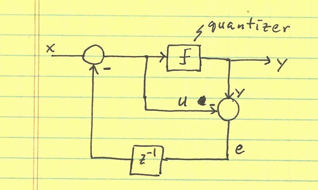
This loop attempts to subtract the error induced by the embedded ADC (called the quantizer). Of course, this error isn’t available until it’s too late. The error e is not available until after the input to the quantizer u passes through the quantizer—at which point, it’s too late to correct the quantizer input u. So, instead, we use the prior error (which is available): The input u to the embedded ADC (called the quantizer) is subtracted from the quantizer output y to obtain the error e. This value is saved in a memory element (z-1) to modify the input x on the next cycle.
This loop attempts to subtract the error induced by the embedded ADC (called the quantizer). Of course, this error isn’t available until it’s too late. The error e is not available until after the input to the quantizer u passes through the quantizer—at which point, it’s too late to correct the quantizer input u. So, instead, we use the prior error (which is available): The input u to the embedded ADC (called the quantizer) is subtracted from the quantizer output y to obtain the error e. This value is saved in a memory element (z-1) to modify the input x on the next cycle.
We find that the output Y is composed of (in the z-domain):
$$ Y + X + (1-z^{-1})E $$
So, the output Y contains X plus a filtered version of the error E. The value (1-z-1) is called the noise transfer function (NTF), since it tells us how much (versus no sigma-delta loop) the noise is transferred to the output. A frequency-domain plot is shown below:
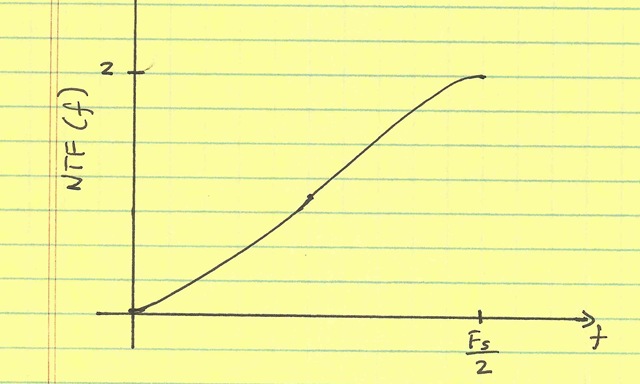
One can see that near dc, the noise is greatly suppressed. However, near Fs/2, it is actually enhanced. This makes intuitive sense: we used the previous estimate of the error to correct the input. If the error is constant (dc), this estimate is good; we have suppressed the noise. However, if the error is alternating (a sinusoid at Fs/2), this estimate is exactly the opposite of what we want; we have actually increased the noise.
This also brings out another feature of sigma-delta loops: the total amount of noise is neither increased nor decreased. The loop simply “shifts” it higher in frequency. This is why sigma-delta loops are called sigma delta modulators—they appear to modulate (shift in frequency) the noise.
In addition, the loop has another benefit: the memory element holds a state that depends not merely on the input, but (rather chaotically) on the quantization error itself. As a result, we don’t see periodic behavior in the quantization error when we have a periodic input. As a result, we see less harmonic distortion in the quantization error, and the quantization error appears more like a white noise (which is then filtered by the NTF). This whitening is more desirable than dither, which increases the total amount of noise (quantization noise + dither noise).
The NTF in this case appeared as a first-order high-pass filter. If more delay elements were added (nth order low-pass filter) in the feedback, the NTF would be an nth-order high-pass filter. Furthermore, this error-feedback topology is usually only used in a digital implementation of the loop (rather than a switched-capacitor/analog implementation). The reason is that in the analog domain, the subtraction y – u is costly. However, in the digital domain it is cheap (actually, free).
While it is intuitive to feedback the error, any loop which suppresses the error for low-frequencies will be equally as effective. These topologies are not as intuitively obvious, but work just as well. I’ll present the alternate analog topology in a future post.