Foster’s reactance theorem states that any reactance $X$ increases as a function of frequency $f$. This is true of the impedance looking into an antenna, where the reactance may be a large part of the overall impedance. The task in matching the antenna (for maximum power transfer and therefore maximum SNR) is to cancel the reactance (or susceptance) and match the resistance.
Unfortunately, this can’t be done over a large range, because as Foster’s reactance theorem states, as soon as you deviate a little from your center frequency, both the inductive reactance of your antenna and the reactance of whatever you’re using to cancel it (most likely a capacitive element) both increase (go toward [amath]+oo[/amath]). So, for every change $\Delta f$ in frequency from the center frequency, your antenna reactance goes up by some amount ${dX_{A}}/{df}\Delta f$, but your matching element’s reactance also goes up by some amount ${dX_{M}}/{df}\Delta f$.
If you had a Non-Foster element, the reactance of your tuning element would go down by some amount $-|{dX_{M}}/{df}|\Delta f$, compensating for the increased reactance of the antenna. You would then have a broadband (or broader) match.
Most attempts to do this have required the use of active elements (such as gyrators) so synthesis a negative impedance. However, I’m wondering if a switched-capacitor circuit can be used to synthesize this Non-Foster reactance. Most analyses of switched-capacitor circuits show that they are synthetic resistors at frequencies far below the switching frequency. However, what does the impedance look like near the switching frequency?
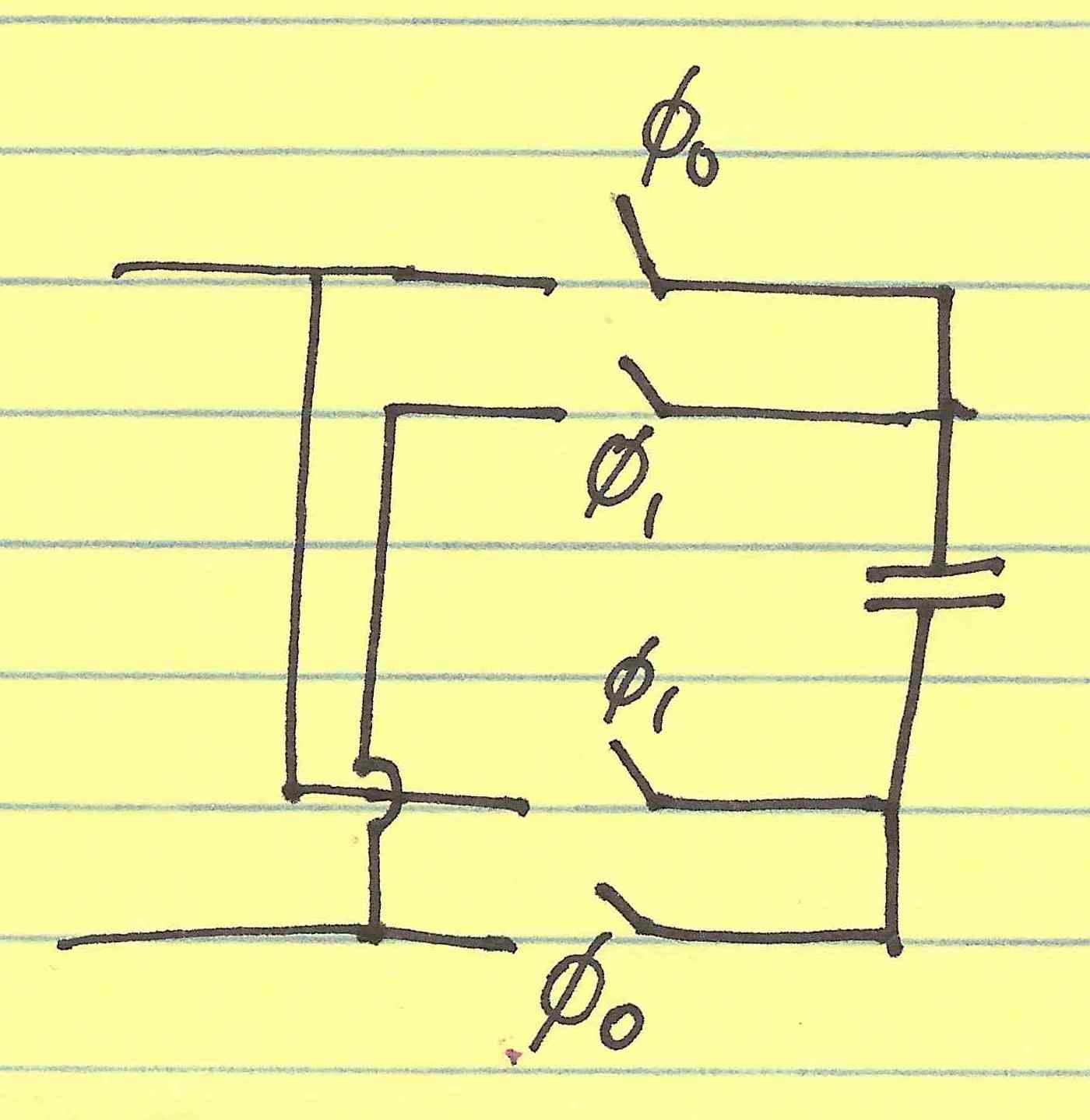
Well, since you’re pumping current into the circuit at exactly the rate of switching, you should see a large voltage. As a result, it should look like a high-impedance near the switching frequency. I would tend to believe that the switching function takes the usual $1/(j \omega C)$ function and modulates it up to the switching frequency. (I haven’t proved this and probably won’t ever prove it.) However, if one thinks about the following picture, the current coming into the capacitor can be seen as the independent variable. Then, the voltage is the regular voltage, except mixed by the switching function. Thus, the $V/I$ ratio should be some modulated version of the fundamental capacitor’s impedance.
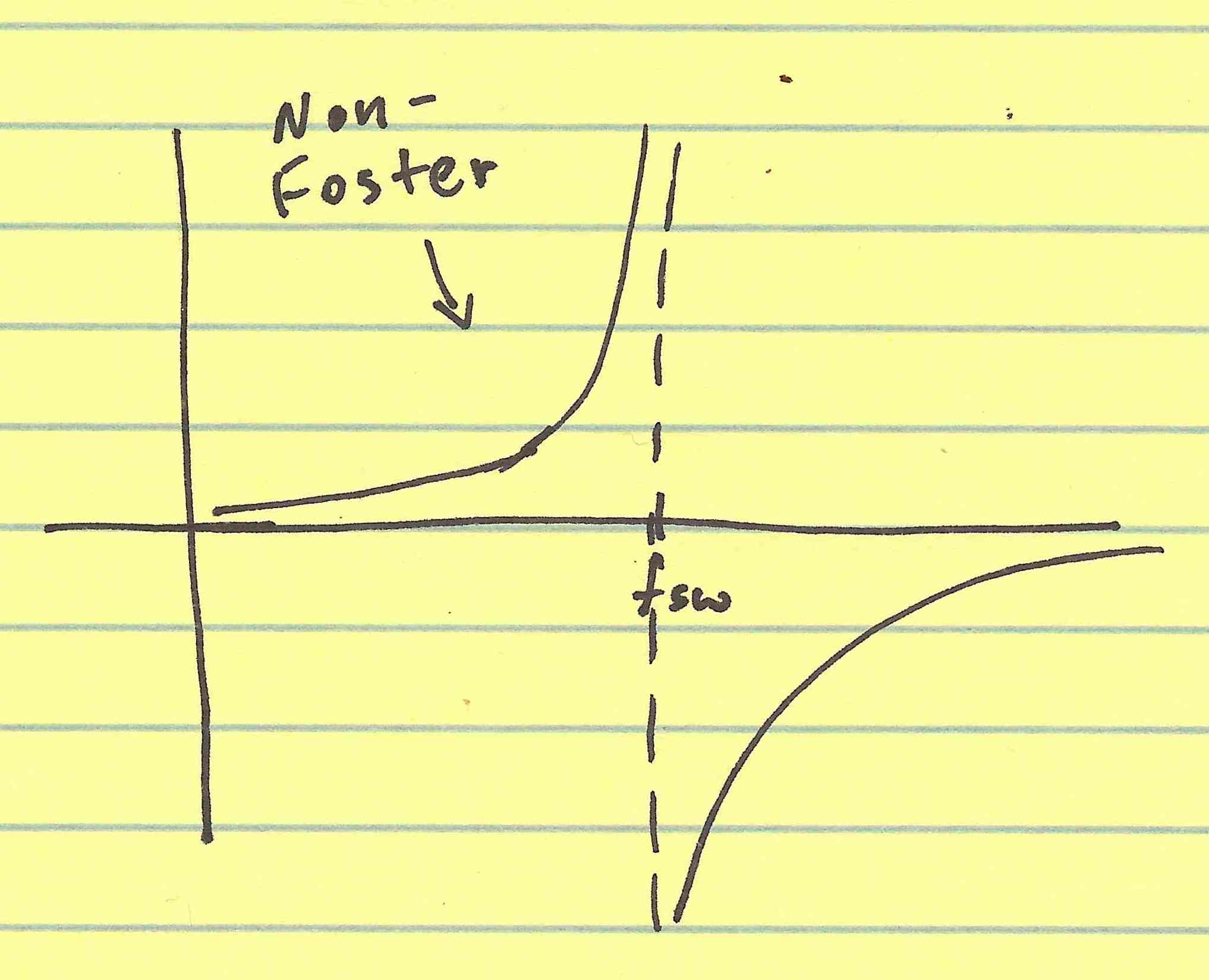
The upshot of all this mixing is that just below the switching frequency, one would have a reactance that’s decreasing. (I’m doing a considerable amount of hand-waiving here, excluding such things as aliases of the switching harmonics.) What’s even cooler about this reactance is that the Non-Foster region is determined by the switching frequency–so, one could move it around just by changing the switching frequency. You’d effectively have a digitally-tunable antenna.
 There are a number of problems with this scheme, most notably the radiation of switching noise and any switched-capacitor noise effects. However, I think it’s worth looking at and building upon.