I’ve been fielding quite a few questions lately about polar modulation. Indeed, polar modulators are theoretically more efficient. However, this does not need to be the case. I will highlight (technically, self-promote) a Cartesian scheme that can produce an RF signal as efficiently as a polar modulator—with fewer implementation issues.
Introduction
In general, we are trying to produce the signal
$$r(t) = x_{I}(t) cos( \omega_{c}t ) – x_{Q}(t) sin( \omega_{c}t )$$
where $x_I$ is the in-phase (I) component and $x_Q$ is the quadrature (Q) of our complex baseband signal. In general, RF transmitters have a modulator circuit which carries out this math. These are called Cartesian modulators and are generally drawn as:
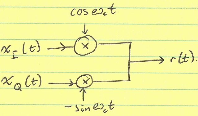
This diagram is meant to be interpreted as a high-level circuit schematic. Namely, the output r(t) is a wire-sum of the the individual mixer outputs.
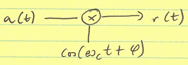
$r(t)$ can also be written as
$$r(t) = a(t)cos(\omega_{c}t – \phi(t))$$
where $a(t)=\sqrt{x_I^2 + x_Q^2}$ and $\phi(t)=arg(x_{I}, x_{Q}) =atan(x_{Q}/x_{I})$. Then, we lose the need to sum the signals and we can simply implement:
Cartesian Inefficiency
The inefficiency of the Cartesian modulator is not in the individual mixers themselves (they are equivalent between Cartesian and polar). The inefficiency lies in the summing of the two mixer outputs: some current flows from the I-mixer into the Q-mixer and is dissipated by the Q-mixer’s output resistance. Indeed, we could get a high efficiency RF modulator if we could stop this current flow. Indeed, if the component mixers were high output impedance (i.e. current sources), this summing could be done efficiently.
Switched-Mode Modulators
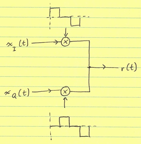
It should be noted that while we desire $x_{I}(t) cos(\omega_{c}t ) – x_{Q}(t) sin(\omega_{c}t )$, what usually gets implemented is $x_{I}(t)p(t) – x_{Q}(t)p(t – T_{c} / 4)$ where $p(t)$ is a square wave at the carrier frequency. This works because $p(t)$ has a component of $cos(\omega_{c}t)$—albeit with some higher order terms. However, these terms can usually be filtered out.
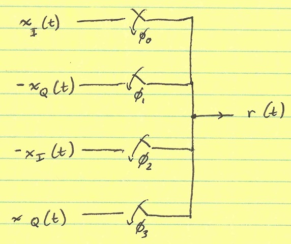
Interleaving
What if, instead of summing the two signals, we interleaved them. That is, we spit out a sequence (at 4x the carrier frequency) of [+ xI, –xQ, –xI, +xQ]? It turns out that this is equivalent to multiplying $x_{I}$ by a [+1,0,-1,0] sequence (which also has a term of $cos(\omega_{c}t)$) and multiplying $x_{Q}$ by a [0, –1, 0, +1] sequence (which has a term of $sin(\omega_{c}t)$).
It turns out in a conventional modulator, that the cases where the I- and Q- LO’s overlap is very inefficient, and it contributes nothing to the output signal power. With the interleaved modulator, this overlap no longer exists. (The $cos(\omega_{c}t )$ term in [+1, 0, –1, 0] is smaller than the term in [+1, +1, –1, –1]. However, we are concerned about efficiency—the ratio of power produced to power dissipated—not absolute output power.)
This can be implemented efficiently by the following switching circuit:
For clarity, I’ve shown the circuit as a single-balanced (single-ended) output, but it can be (and should be) implemented as a fully differential output.