Introduction
You’ll notice that this post has Matt Miller listed as the author. Poojan requested Matt’s comments on his differential circuit post. Poojan was impressed with my comments enough that he decided to make it a follow-up post. So, this post is co-written by both Poojan and Matt.
Watch Full Movie Online Streaming Online and Download
Gain
Some of you asked whether the differential circuit being biased at half the current therefore has half the transconductance, and therefore lower gain. The answer is that it depends.
The single-ended circuit has an output current i_o = g_m * v_i. In many cases, the only thing this circuit can drive is a single-ended load Z_L.
The differential circuit has an output current i_{o+} = g_m * v_i/2; i_{o-} = -g_m * v_i/2.
So, the question comes down to whether we can subtract the two currents i_{o+} and i_{o-} to produce a differential current. Although one can think of it that way, it’s really more accurately to define the current flowing out of one side and into the other. The current, therefore, doesn’t change. However, all other things being equal, the load on the differential circuit will be 2Z_L. Therefore, the gain is the same.
Free Lunch
Some of you questioned the 4x boost in dynamic range that the differential circuit gives over its single-ended counterpart. While I made some mistakes with the equations (they’re fixed now), the result was correct: the differential circuit does have 6 dB higher dynamic range. Where did this come from? Well, it’s the basic advantage of the differential circuit: while a single-ended circuit can only swing +/- Vx, a differential circuit (where the output is defined as the difference of two single-ended circuits) has a swing of twice that: +/- 2Vx. Having twice the voltage is equivalent to 4x the power (and in both cases, that’s 6 dB improvement).
There’s No Such Thing
If some of you feel that this can’t be possible, please keep in mind the long disclaimer at the beginning of the last post: there are no universally better circuits. There are only certain circuits that are better suited for certain applications. In this case, the differential circuit gets its benefit from improved output range. However, the gain doesn’t change. Therefore, there’s an intrinsic assumption here: the circuit will tolerate a higher output, but there’s no gain to make the output higher. We didn’t intrinsically get double the gain, so we can’t take advantage of the dynamic range without sticking some gain ahead of the circuit.
That’s requirement is perfectly fine in a lot of cases. In many cases, you already have a ton of gain and automatic gain-control (AGC) ahead of the circuit. In that case, the AGC range can be reduced (possibly improving overall performance). This is true (for example) in the baseband filter at the end of an RF line-up. For that application, the figure of merit really is dynamic range. Similarly, in an ADC, the extra dynamic range might mean more effective bits of resolution.
Cheap Lunch
We’ve given the impression that the dynamic range can’t be leveraged in (for example) an RF LNA. Turns out that it can—for relatively cheap (although not for free). If one were to stick a 1:4 (impedance ratio) balun ahead of the circuit, one would get this voltage gain for relatively cheap (meaning, the cost of the balun). In many cases, some form of impedance transformer (matching network) is required anyway, so putting a balun in isn’t a great cost.
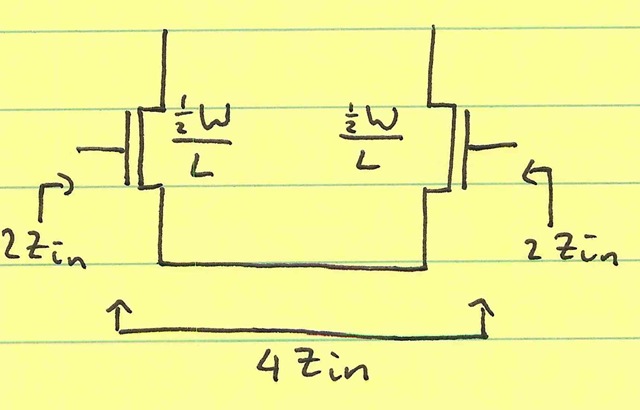
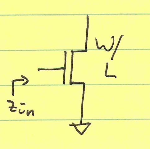
The balun doubles the voltage but quadruples the output impedance. This is actually a good thing: the differential circuit has 4x the input impedance of the single-ended circuit. Let’s call the single-ended circuit’s input impedance Z_i. The differential circuit has 2Z_i input impedance on each side (we’ve cut the single-ended circuit in half). However, these input impedances get stacked to form the fully differential input impedance, so we get 4Z_i as the input impedance of the differential circuit:
 versus