Introduction
Consider our usual continuous-time sigma-delta (CTSD) ADC:
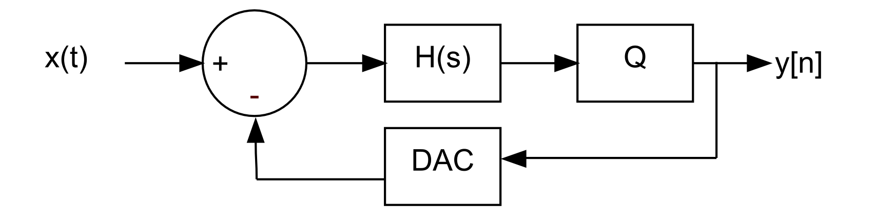
x(t) is the analog input and y[n] is the digital output and feedback signal that drives the DAC. H(s) is the loop filter and Q represents the quantizer.
One of the main difficulties with continuous-time sigma-delta’s is that when the digital output does not match the analog feedback, an error is created. This condition occurs when a very weak signal appears at the quantizer input, causing the quantizer to eventually go to +1 or -1 but to do so in a very slow and almost idle manner.
An example is shown below:
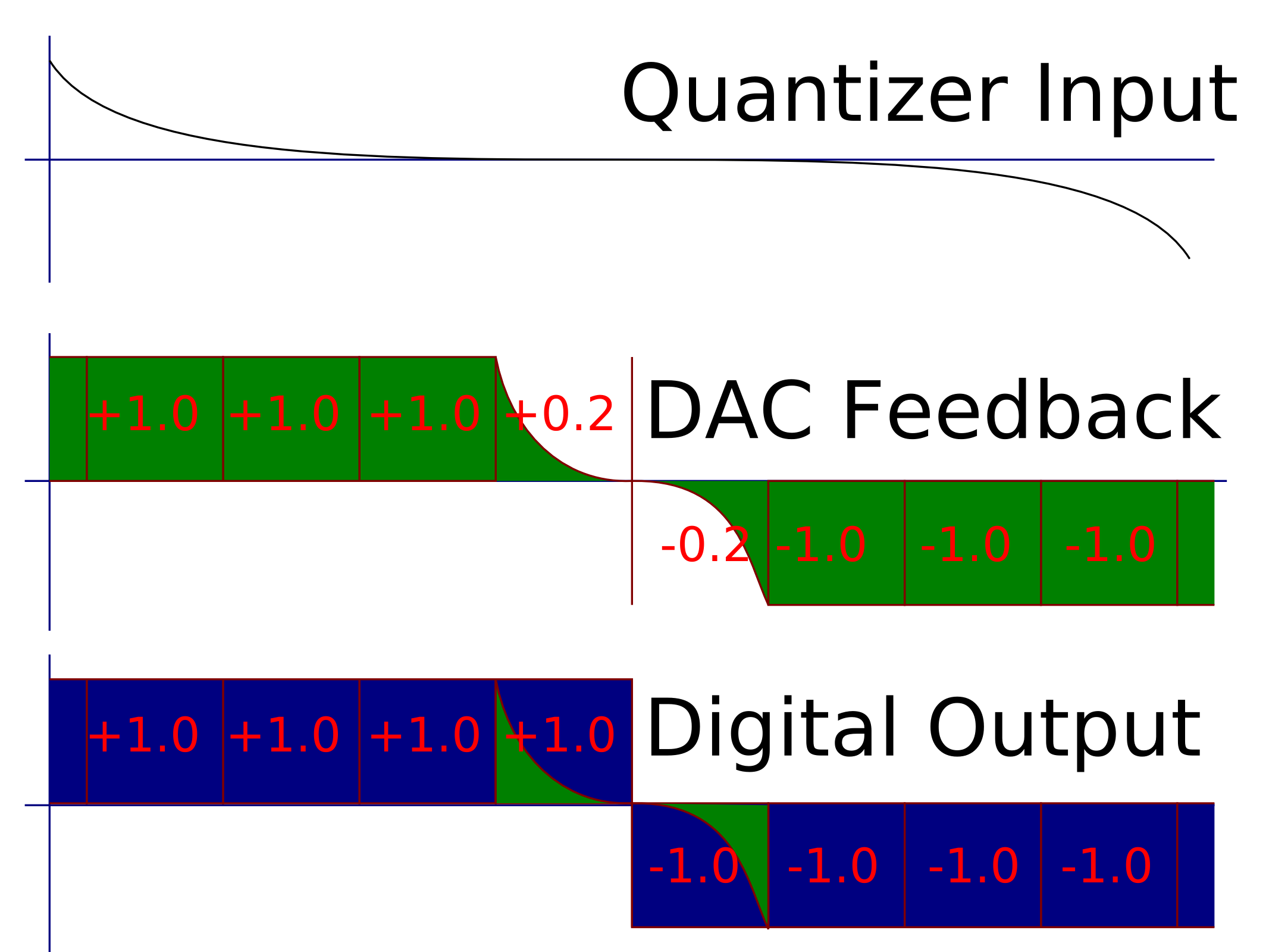
Some may wonder why, when the same signal is sent to both the DAC and to the digital world, the digital interprets the signal as a full +/-1.0 and the analog (DAC) represents the signal as +/-1.0 most of the time, but sometimes +/-0.2. The reason is that its impossible for the digital logic (recovery filtering) to interpret the output as anything but +/-1.0. There is additional logic and latches within the digital recovery filter that will enforce a hard decision on the output. This decisiveness is not the case with the analog. Even a switched-mode DAC will transition smoothly from +1.0 to -1.0.
This error is catastrophic to the CTSD ADC because the DAC feedback accurately represents the input signal x(t). However, the digital output does not. The digital output yd[n] can be viewed as a sum of the analog feedback ya[n] plus an error: yd[n] = ya[n] + e[n]. This error e[n] is signal-dependent and can mix out-of-band noise back in band.
Solutions
I’ve seen several approaches at correcting this error.
The simplest of these is to insert more latching stages within the loop. These latches as I’ve discussed before utilize positive feedback to gain up the signal and force a hard binary decision. The penalty is that the latches insert additional delay in the loop. This extra delay limits the stable bandwidth of the sigma-delta. Some of the delay can be compensated by modifying the noise-shaping filter. However, the result is still a reduction in bandwidth or SNR.
My preferred solution is to utilize these additional latches, but also to add an additional lap that does not incur the additional delay:
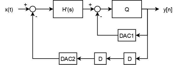
The primary DAC (DAC2) subtracts from the input. Errors on this DAC (relative to the digitized output) appear as if they are errors on the input. However, the secondary DAC (DAC1) feeds the first sample of the noise-shaping filter to the input of the quantizer. This DAC will inject indecision errors (relative to the digitized output), but its errors are shaped by the loop (they appear just like quantization noise).
The authors of the paper which introduced me to this concept (I will post a reference when I find it) didn’t divulge the math involved. Technically, it was Matt Miller who introduced me to this concept by citing the paper. Basically, since the auxiliary DAC (DAC1) submits the first sample, the noise-shaping filter must be modified to omit the first sample.
I’ll go through the math in the next installment. Get notified by RSS or by email.
[…] « Dual DAC CTSD | Wider Bandwidth and Higher SNR — Part 1 Polar vs Cartesian RF Modulator Efficiency » […]